Pedestrian Crossing for the Raspberry Pi v0.5
author: Opabinia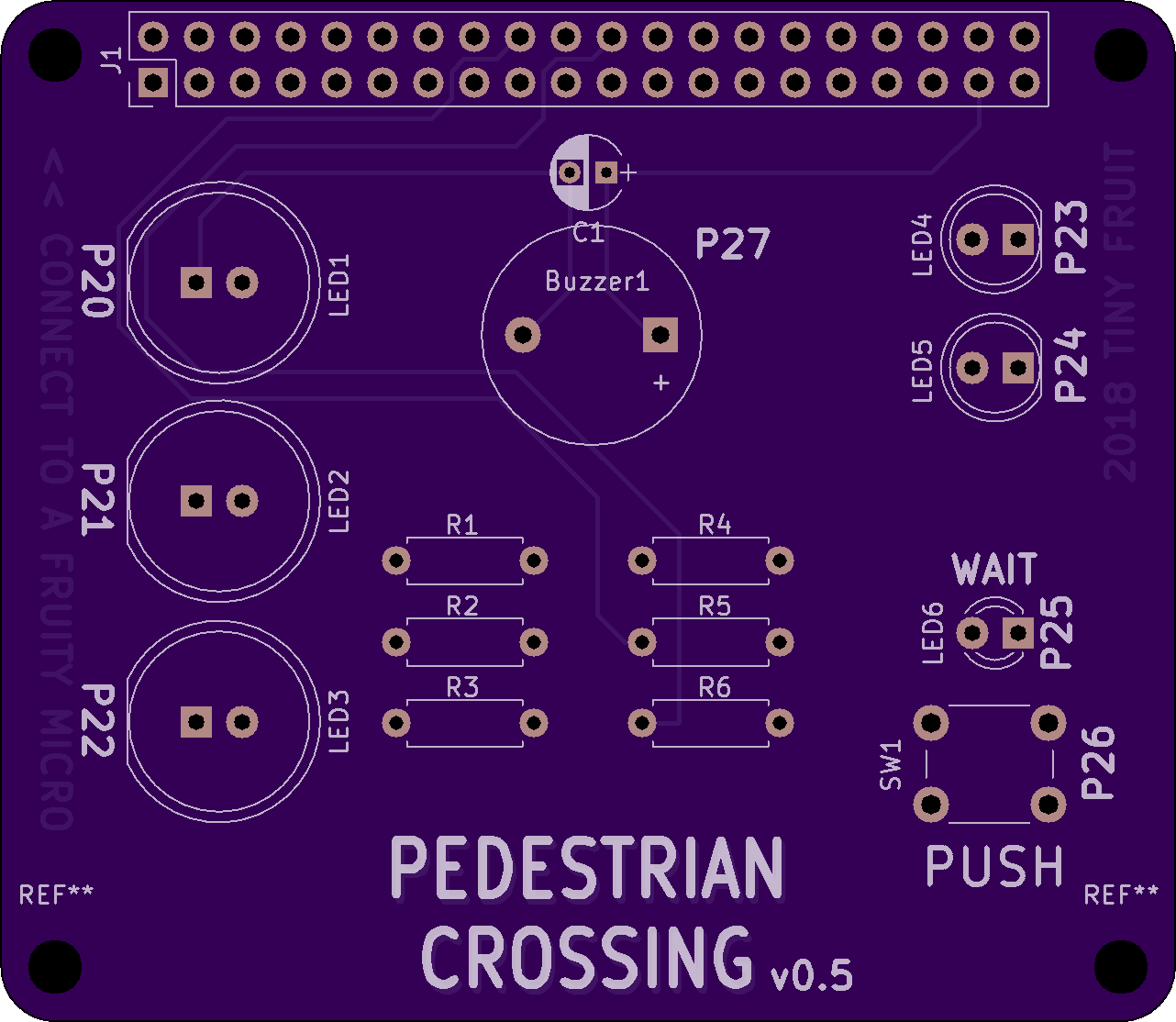
2 layer board of 2.56 x 2.23 inches (65.1 x 56.6 mm)
Uploaded:
February 20th 2018
Shared:
March 14th 2018
Total Price:
$28.55
Warning! This board hasen’t been tested yet, there might still be issues that needs to be addressed. Watch out for future revisions!
Note (180314): A previous and tested version of this design is available here: https://oshpark.com/shared_projects/wrF9XJDk
The quick and dirty mockup code is available here: https://github.com/overengen/Pedestrian_Crossing_for_the_RPi
The pin layout has been changed in this later revision of the PCB, but this is easily corrected in the program by swapping out a few numbers accordingly.
Update: v0.5 - Adjusted position af the mounting holes and dimensions around the corners that was slightly of and smaller in arc.
Update: v0.4 - Rearranged som of the graphic, redesigned the wiring and pinout to make them follow a more logical order and easier to use while programing.
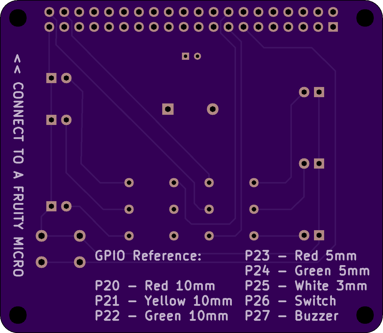
GPIO Reference:
P20 - Red 10mm
P21 - Yellow 10mm
P22 - Green 10mm
P23 - Red 5mm
P24 - Green 5mm
P25 - White 3mm
P26 - Switch
P27 - Buzzer
This is my first attempt to design a PCB for the Raspberry Pi. It’s a dead simple design and supposed to fit on top of a Raspberry Pi (65x56.5mm). With a bit of coding the Raspberry Pi should be able to control all the LEDs, the buzzer and read the push button. My intention is to use this as a base for a coding project at school. Pin numbers (connecting to the switch, the buzzer and the LEDs) are written on the surface of the PCB as a reference in order to make coding a bit easier.
BOM:
3 x 10mm LEDs (red, yellow, green).
2 x 5mm LEDs (red, green).
1 x 3mm LED (yellow or white).
1 x Switch 4pins, 6mm.
1 x Buzzer
6 x Resistors (~50 Ohm)
1 x Connector (20x2)
Warning! This board hasen’t been tested yet, there might still be issues that needs to be addressed. Watch out for future revisions!
Note (180314): A previous and tested version of this design is available here: https://oshpark.com/shared_projects/wrF9XJDk
The quick and dirty mockup code is available here: https://github.com/overengen/Pedestrian_Crossing_for_the_RPi
The pin layout has been changed in this later revision of the PCB, but this is easily corrected in the program by swapping out a few numbers accordingly.
Update: v0.5 - Adjusted position af the mounting holes and dimensions around the corners that was slightly of and smaller in arc.
Update: v0.4 - Rearranged som of the graphic, redesigned the wiring and pinout to make them follow a more logical order and easier to use while programing.
GPIO Reference:
P20 - Red 10mm
P21 - Yellow 10mm
P22 - Green 10mm
P23 - Red 5mm
P24 - Green 5mm
P25 - White 3mm
P26 - Switch
P27 - Buzzer
This is my first attempt to design a PCB for the Raspberry Pi. It’s a dead simple design and supposed to fit on top of a Raspberry Pi (65x56.5mm). With a bit of coding the Raspberry Pi should be able to control all the LEDs, the buzzer and read the push button. My intention is to use this as a base for a coding project at school. Pin numbers (connecting to the switch, the buzzer and the LEDs) are written on the surface of the PCB as a reference in order to make coding a bit easier.
BOM:
3 x 10mm LEDs (red, yellow, green).
2 x 5mm LEDs (red, green).
1 x 3mm LED (yellow or white).
1 x Switch 4pins, 6mm.
1 x Buzzer
6 x Resistors (~50 Ohm)
1 x Connector (20x2)
